|
|
Horstman X5 Clutch |
Foreword
The X5 one disc clutch is engineered for Briggs Jr kart racing. This manual will help you obtain the correct setup for each class of competition. The manual also provides instructions regarding the periodic maintenance required to keep the clutch performing at top level.
Rules
The X5 meets prescribed 4 cycle clutch rules for specific karting rulebooks however the X5 is smaller than permitted by one organization. User assumes responsibility for compliance with local or national kart racing clutch rules.
Warning!!!
When the engine starts the clutch and chain may spin at high speeds if brake is not applied. Do not operate vehicle without proper guards in place. Do not attempt to adjust, repair, or lubricate clutch or chain with engine running. The cerametallic friction disc has a very aggressive lock up. During slow take offs when leaving the grid it is possible to have clutch chatter that will not effect performance on the race track.
Installation
It is better to mount the clutch with the sprocket facing the engine because stall speed adjustment can be accomplished without removing the clutch. Mounting the clutch with the sprocket facing away from the engine requires the optional spacer kit p/n 477736 for proper clearance between the levers and the side of the engine.
Steps for inboard installation
- slide clutch onto crankshaft … if clutch does not slide freely then sand nicks or burrs from the crank
- align keyway in clutch with crank keyway .. insert key (item 20) … do not force key … file any burrs from clutch or crank keyway …Also you may need to sand or file the side of the key a small amount
- slide spacer (item 19) onto crankshaft
- install lock washer (item 22 and flat washer (item 21) onto bolt (item 23)
- thread bolt into crank and tighten firmly (150 inch pounds)
Stall Speed
Stall speed is the RPM that the clutch locks up solid. For top performance it is important to adjust the stall speed to match the peak torque of the engine. This allows the engine to operate within its power band for quicker acceleration. Factors that affect stall speed such as metallurgy, friction material, lever dynamic, and surface finish are engineered into the product therefore you only need to be concerned with the number of washers on the levers and adjusting the spring tension. The ideal stall speed adjustment will result in the fastest lap time.
Stall Speed Adjustment
Adjusting the stall speed of the clutch may be intimidating if you are a newcomer to the sport however it is relatively easy to learn. A tachometer with memory is needed to obtain accurate data. Setting the clutch stall speed to the engine’s peak torque should produce the fastest lap times. If the stall speed is set more than 100 rpm above peak torque lap time may be slower. Of course if the stall speed is below peak torque lap time may also be slower.
Steps
1. Install the recommended color-coded springs from the Stall Speed Chart and adjust the height (fig 2)
2. Go onto the track and observe tachometer reading while kart is accelerating. The stall speed is the rpm reading when the clutch engages solid and the kart begins accelerating rapidly. Warning! If the stall speed is above the range on the chart below you must exit the track in a safe manner and return to your pit to adjust the stall speed lower to prevent overheating the clutch. If the stall speed is within the prescribed range on the chart you may drive enough laps to get the engine up to proper temperature and get comfortable with the track configuration. Run about five to ten laps to establish your performance base line.
3. Return to your pit and look at the tachometer data. Note the Max RPM, MPH, lap times, and stall speed.
4. Adjust stall speed if necessary and make another test session. Keep making clutch adjustments until you determine the best stall speed for the fastest lap. Now you can look at gear ratio changes as well as chassis adjustments to test for even faster lap times.
Stall Speed Chart
The chart is a guideline only as various weight/spring combinations can produce comparable results. Adding washers and/or installing weak springs will lower the stall speed. Removing washers and/or installing strong springs will raise stall speed.
|
Class |
Weight |
Spring color |
Stall Speed Range |
Initial spring height setting |
|
Briggs Jr Sportsman 1 .425” purple restrictor |
4 washers |
black |
2800-3000 |
.210” |
|
Briggs Jr Sportsman 2 . 500” turquoise restrictor |
3 washers |
black |
3000-3200 |
.190” |
|
Briggs Jr .575” gold restrictor |
3 washers |
Yellow |
3600-3800 |
.210” |
|
Briggs Jr Lite & Hvy unrestricted |
3 washers |
Yellow |
3800-4000 |
.190” |
How to raise Stall Speed
There are three ways to raise the stall speed
- Spring adjustment (clockwise)
- Less washers on levers
- Install stronger springs
To raise stall speed by increasing the spring tension you must dial the five adjusting screws equally clockwise. ¼ turn will raise the stall speed about 85rpm. If you can’t get thecorrect stall speed within the spring adjustment limits (Fig 2) then remove washers from the levers and reset the springs.
How to Lower Stall SpeedThere are three ways to lower the stall speed:
2. Install weaker springs 3. Add washers |
Figure 1
|
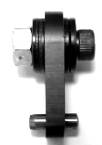
To lower stall speed by decreasing the spring tension you must dial the five adjusting screws (item 17) equally counterclockwise. ¼ turn will lower the stall speed about 85 rpm. If you can’t get the correct stall speed within the spring adjustment limits (Fig 2) then install weaker springs. Figure 1 shows lever with 4 washers installed.
|
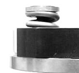
Spring Adjustment Limits Warning!!!! The springs in this clutch have afinite range of travel therefore adjustment limitsmust be followed. (Fig 2) Do not adjust above the maximum height .225” because the springs(item 15) will not have enough tension to keepthe adjusting screws in place. Do not adjust below the minimum height .170” because the springs will coil bind. Coil bind is when the spring is fully compressed and acts like a solid object with zero travel. Coil binding of the springs will prevent the pressure plate (item 10) from moving the prescribed distance to allow complete lock up and excess heat will quickly ruin the clutch. |
Measure from top of spring to lever support
Figure 2 |
¬¾¾top of spring
¬¾ lever support Maximum .225” |
Air Gap
Air gap is the space between the disc (item 9) and the pressure plate (item 10). Correct air gap will allow a neutral mode for starting the engine. The air gap is preset at the factory at .028” +/- .006” . Air gap adjustment is not necessary in this clutch however when regrinding the pressure plate or drive hub friction face it is important to keep the air gap within tolerance. Therefore grinding the face of the pentagon shaped shoulder may be necessary.
Cleaning
Remove clutch from engine when cleaning. Use disc brake spray cleaner for best results. Do not use solvents, gasoline, water, or household cleaners as contamination of the friction disc can occur. Wear safety glasses and protective gloves when cleaning and performing maintenance.
Disassembly
| 1. Remove snap ring (item 1) | 7. Remove the five ¼-28 cap screws (item 18) |
| 2. Remove outer thrust washer (item 2) | 8. Remove lever support (item 11) |
| 3. Slide drum (item 5) off drive hub | 9. Take off pressure plate (item 10) |
| 4. Remove thrust washer (item 6) | 10. Remove friction disc (item 9) |
| 5. Remove thrust bearing (item 7) | 11. Remove levers (item 13 and dowel pins (item 12) |
| 6. Remove spring adjustment screws (item 17) and springs |
Maintenance
For peak performance it is important to clean and apply multipurpose grease to the sprocket bearing and thrust bearing after each race event. Also inspect the following:
Drum and sprocket (item 4&5)
Check the four screws that attach the sprocket to the drum and if loose apply loctite and tighten to 85 in lbs. Check drum for wear in slots or any cracks where bolted to sprocket and replace. Replace sprocket when teeth are worn to a point as chain will keep coming off. Replace any bearing that will not spin freely. Replace any washer that is not smooth.
Drive Hub (item 8)
Check for wear or score marks where friction disc makes contact. Remove score marks or glaze with 100 grit sandpaper. Replace hub if keyway is cracked.
Friction Disc (item 9) Most important !!!!
A friction disc is subjected to high surface heat from friction during engagement cycles and will wear and glaze. Deglazing the disc will improve performance and can be accomplished easily. Just lay a clean sheet of 100 grit sandpaper onto a flat surface then place the disc onto the sandpaper. Now make a figure 8 motion while sanding the disc. Most glazing can be removed in about 60 seconds . Sand both sides of the disc. A disc will have useful life until worn to .138” overall thickness.
Lever Support (item 12)
The lever support is made from alloy aluminum and has a hard coating for corrosion protection and wear resistance. Check after every ten race events for excessive wear in the slots where the levers rub. Replace when deeply worn.
Levers (item 13)
The levers are made from hardened alloy steel and will last a long time. After every ten race events check for wear at the pivot hole and replace when oval shaped.
Dowel pins (item 12)
Subject to high forces from levers. Replace after a season of racing. Tip … apply a light coat of anti-seize lube to the dowel pins every five races and the levers will move freely and last longer
Springs (item 15)
Springs are subjected to heat and stress and must be inspected every five races. When free length is below .475” replace the springs. Warning: use genuine Horstman springs …. Aftermarket springs are not cryogenically treated nor in most cases shot peened or made from the best alloy therefore they will make your clutch inconsistent.
|
Item No |
Part Number |
Description |
Units Required |
|
0 |
490001 |
Spacer , use with 11T #35 clutch only |
1 |
|
1 |
463000 |
Snap ring, 12T-23T clutch |
1 |
|
2 |
490003 |
Washer, 1 1/8” diameter fits 12T & 13T #35 & 15T #219 clutch |
1 |
|
|
490004 |
Washer, 1 ¼” diameter fits 14T-23T #35 & 17T-23T #219 clutch |
1 |
|
3 |
463600 |
Bearing, bronze fits 11T #35 clutch |
1 |
|
|
463400 |
Bearing, bronze fits 12T & 13T #35 & 15T #219 clutch |
1 |
|
|
463500 |
Bearing, roller fits 14T-23T #35 & 17T-23T #219 clutch |
1 |
|
4 |
See chart |
Sprocket Kit, includes bearing and hardware |
1 |
|
4A |
477701 |
Screw, 10-32 button head |
4 |
|
5 |
See Chart |
Drum Kit, includes sprocket, bearing and hardware |
|
|
5A |
477702 |
Drum only |
1 |
|
6 |
490035 |
Thrust washer, 11T #35 Clutch only |
1 |
|
|
480078 |
Thrust washer, 12T-23T Clutch |
1 |
|
7 |
490036 |
Thrust bearing, 11T #35 Clutch only |
1 |
|
|
480079 |
Thrust bearing, 12T-23T Clutch |
1 |
|
8 |
477725 |
Drive hub, fits 11T #35 Clutch only |
1 |
|
|
477726 |
Drive hub, fits 12T-23T Clutch |
1 |
|
9 |
477729 |
Friction disc, cerametallic |
1 |
|
10 |
477727 |
Pressure plate |
1 |
|
11 |
477728 |
Lever support |
1 |
|
12 |
480086 |
Dowel pin |
5 |
|
13 |
490008 |
Lever |
5 |
|
14 |
477732 |
Weight kit, 5 bolts, 20 washers, 5 lock nuts |
1 |
|
15 |
3130Y |
Spring, yellow high tension (Set of 5 blueprinted) |
1 |
|
|
4650Y |
Spring, black medium tension (Set of 5 blueprinted) |
1 |
|
|
5142Y |
Spring, blue ,low tension (For stall speed below 2800) Set of 5 |
optional |
|
16 |
477733 |
Retainer, color gold |
5 |
|
17 |
334800 |
Screw, 10-32 x ¾ flat head |
5 |
|
18 |
477734 |
Screw, ¼-28 x ¾ socket head |
5 |
|
19 |
477731 |
Spacer, fits all X5 clutch models 11T-23T |
1 |
|
20 |
465100 |
Key |
1 |
|
21 |
465200 |
Washer, flat |
1 |
|
22 |
465500 |
Washer, lock |
1 |
|
23 |
465300 |
Bolt |
1 |
|
|
477735 |
Spanner wrench, color gold |
optional |
|
|
477736 |
Outboard Spacer kit |
optional |
Patents pending
