

This clutch is a 3 disc 6 spring clutch. It would be used in the adult stock briggs flathead class on a track requiring heavy clutch usage. Heavy clutch usage would be a result of either a heavy kart such as the Super Heavy or Champ class, or a track that is small and requires frequent engagement of the clutch throughout the race.
Fits 3/4" crank shaft.
Includes mounting hardware.
FACTORY SETTINGS
Engagement: 4000 RPM
Weights: 1 Bolt outer hole of every lever
Springs: Red
Spring Height: .225"
Choose sprocket under options.
Setup information under "More Details".
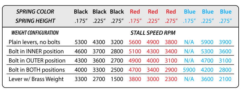
Model Applications - Spring and weight combinations may be interchanged to suit the individual application. As you make your selections be aware that the heavier the weights and the stiffer the spring, the more positive the engagement becomes. However, with stiff springs and heavy weights, the clutch will have to drop well below its engagement RPM before the clutch will once again release. Stiffer springs are springs with a larger wire diameter and they will give higher stall speeds. Below is a chart with the common weight and spring combinations that we recommend on the Bully clutch.
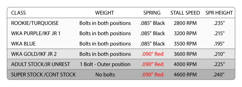
The shaded areas above designate the "basic" weight package. All two disk clutches in the same shade only require spring height adjustments for class changes. The engagement RPM’s found with the spring heights may vary with each individual, and are listed as a reference point only. The actual engagement should be at or up to 200 RPM’s above the peak torque of the engine.
Stall speed is the reading shown on the tach as the kart is accelerating from a slow speed before the clutch has become a locked couple.
As the springs are adjusted clockwise, the tension on the springs is increased and the stall speed is raised. The inverse is true of turning the springs counter clockwise, as this will lower the stall speed.
We have found from extensive testing with a computerized accelerometer that the greatest rate of acceleration will occur when the clutch engages at the torque peak of the motor. However, it also should be pointed out that the addition of the clutch to an engine may change at what RPM your engine produces its torque peak. (Usually it moves up 100 to 200 RPM) Also, a given clutch set up will be most efficient with a given amount of torque and engagement RPM. Figure 3 provides some information for anyone looking to deviate from the above settings.
When setting stall speed we suggest making your adjustments in 1/4 turn increments at a time. When testing for your stall speed, use extreme caution as to not over heat the clutch. Next to contamination of the friction disks, heat is the clutch’s biggest enemy so be sure to let the clutch cool down completely between stall speed tests.Installation.
When installing the Bully clutch, the drive sprocket should be installed facing toward the engine. Even though the clutch will have equal performance installed in either direction, the life of the aluminum clutch basket will be much shorter if the clutch is installed with the sprocket outward. Additionally, the clutch adjustment springs will be more accessible when the clutch is installed correctly.
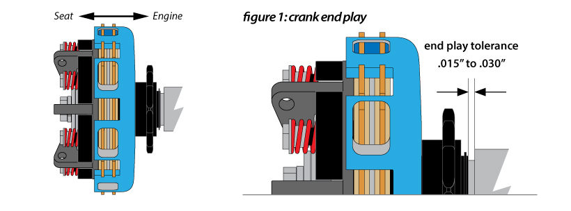
When installing your clutch make sure there is a minimum of .015” and maximum of .030“ end play. After tightening your clutch to the engine, end play can be checked with a feeler gauge between the end of the drive hub and the crankshaft step. See Figure 1. Reducing end play is done by using the .035” shims included, part # 151-002. If the crankshaft is short it will need to have the end play increased by shimming out the 098-015 aluminum washer against the end of the crankshaft. This can be done by placing a washer against the end of the crankshaft that allows the drive hub to slide over it. Not having enough end play my cause permanent damage to your clutch.
Clutch disc break in.
The clutch discs require a period of break-in in order to achieve maximum clutch performance. During this time the outer surface of the linings becomes hot and the microscopic pores of the lining material will burnish themselves to a stable condition. The friction material used in the manufacture of the Bully clutch discs will cause the discs to have more bite as the clutch gets hot. The bite from the disc will also continue to increase throughout the life of the disc.
The break in process should be done when the clutch is new and also after each time the clutch is disassembled or rebuilt. This can be done with the kart on the stand. The break in process of the clutch is similar to the break in of your motor after it has been rebuilt. The goal of the process is to gradually build temp in the clutch at short intervals with cooling between the intervals. If you have a tire temp gun it works great for this process. Engage the clutch and bring the temp up to about 250 degrees and then allow it to cool down, engage the clutch again and bring the temp up to about 300 degrees and again allow it to cool down. Continue this process until you bring the clutch up to approximately 400 degrees. This entire process should take about 4 to 5 minutes.
Air gap.
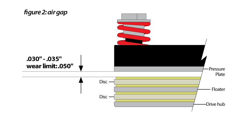
The air gap is the clearance between the friction disks. It is measured with a common feeler gauge and is stated in thousandths of an inch. When new, the Bully clutch is preset between .030” and .035”. As the friction disk wears, the air gap may increase to the wear limit of .050”. When this dimension is reached a shim located under the activator plate should be removed to restore the air gap back to the original dimension. See Figure 2.
Spring height.
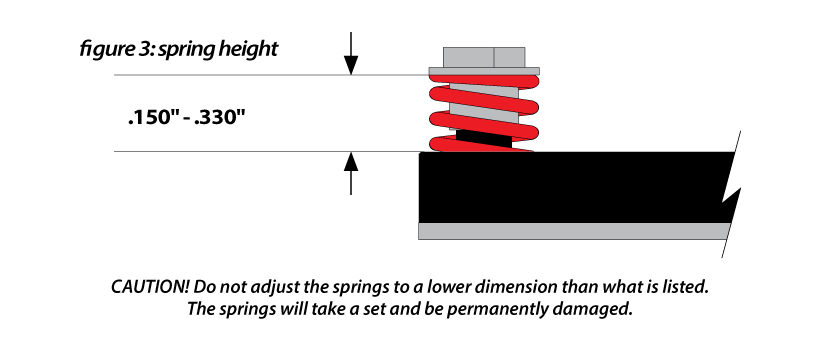
As mentioned earlier, spring height will effect the engagement RPM of the clutch. We suggest making equal adjustments to all 6 springs of 1/4 turn increments at a time. The spring diameter, preload, weight package, engines power and several other variables all will effect how much of an RPM change is found with a 1/4 turn change but an average change will be approximately 100 RPM. Turn the spring adjustment clockwise for more slip and counter clockwise for less slip. The range of adjustment should be between .150” and .330”. This is the distance between the bottom of the spring retaining washer and the top of the activator plate.
See Figure 3.
Theory of operation and dialing in the Bully clutch.
For theory sake lets suppose that the outer clutch basket is constrained and not allowed to rotate such as would occur if the brake was held on tight. When the throttle is opened, the engine will come up to a certain RPM, the clutch will engage and a point of equilibrium will be found......At this point of equilibrium, or stall speed, the entire amount of torque being produced by the engine is being transferred into the clutch. What RPM this occurs at is controlled by 4 variables. Namely the weight of the levers, applied tension of the springs, the coefficient of friction between the friction disks and the amount of torque the engine is producing. A change of each of these variables has it’s own unique effect on the engagement quality of the clutch. As a guideline, lighter levers and less spring tension performs best on motors with lower peak torque values and on tracks where the clutch is continually cycled through its slip range. Heavy levers and high spring tensions will perform best on motors with high torque values and on tracks that require a good launch on the start. If levers are too light for the torque available, the clutches point of equilibrium will be inconsistent and the transfer of power will be inefficient. If the clutch has too much weight on the levers, or the coefficient of friction of the discs is too great for the torque of the engine, a chatter will be produced by the clutch. Chatter is an attempt by the clutch to create a complete lock-up. If the engine does not have enough torque to maintain its RPM, the clutch slows.. releases..the engine speeds back up.. and the resultant chatter is from this process repeating itself very rapidly. Chatter, if left unchecked will destroy a clutch in just a matter of minutes.
Spring color and height recommendations.
Our recommended starting points for spring height and lever/weight combinations on a motor with average torque.
What the spring color and height chart cannot allow for is the coefficient of friction available from the friction discs. The amount of friction produced by the discs may vary. The biggest culprit to friction reduction is from contamination of the discs themselves. The most common forms of contamination are chain oil, moisture and dirt. In most instances the clutch discs will run hot enough to burn off most of these contaminates, however, if the discs become contaminated the clutch may lose its positive feel while also losing some of its ability to transfer power. In the real world, friction discs will not always be able to work in an uncontaminated environment. To cure a soft engagement and restore the clutches ability to transfer power you may want to add weight to the levers. Follow this by readjusting your springs IN, clockwise, until your ideal engagement point is once again found.
The other side of the above condition is too much disc friction. This can occur from a very rapid break-in, very low humidity conditions, rust, or when certain cleaners have contaminated the friction discs. This condition will result in a clutch chatter and if left unchecked may cause mechanical damage to the clutch. To cure a chatter, first remove weight from the levers (if present). If all of the weight is removed from the levers and a chatter is still present, check all springs to insure equal spring height settings.
MAINTENANCE.
The clutch should be protected from moisture and dirt as much as possible. It is important that a small amount of lubrication is provided to the chain. However, too much lubrication can cause the lubricant to migrate to the friction disks and render them useless. So, oil the chain sparingly. The clutch should be cleaned after each race night. To clean your clutch we recommend taking the sprocket/ basket assembly off the clutch. Take the 2 pieces and soak them in a bath of acetone for about 10 minutes. After soaking, spray the clutch out with air, re-lube the sprocket bearing with a small amount of Vaseline and reinstall on the motor. Periodically the air gap and disc thickness should be checked but we do not recommend disassembling the clutch except to change the air gap or rebuild the clutch.
The thrust bearing located in between the sprocket and the clutch hub should be run dry. Of course its life would be extended by lubricating it, but the lubrication from this bearing is most likely to contaminate the friction discs. Since the price of replacing the thrust bearing is very low compared to the price of friction discs, we recommend that this bearing be run dry. The friction disks should be replaced when their thickness becomes less than .110” or when the square outer drive prongs become deformed. A chatter condition in the clutch will cause almost immediate damage to the friction disk drive prongs and the basket.
The pressure plate and the clutch hub should periodically be checked for warpage and straightness. If in doubt, they should be re-ground or replaced.
Levers require visual inspection each time the clutch is disassembled. Look for flat spots developing on the nose of the lever. By the nose, we are referring to where the lever contacts the pressure plate. If any noticeable wear is seen, the lever should be replaced. Also make sure that the lever is able to rotate freely on the dowel pin.
Important sprocket information.
Bully Sprockets are manufactured using the highest grade of materials, CNC machining and heat treat processing. In an effort to give your sprocket the best life expectancy and performance, we offer the following tips.
The sprocket has a removable needle bearing specially designed for applications with minimal lubrication. A small amount of lubricant should be applied to the bearing prior to installation but if you can see the lube on the needle rollers, you have probably used too much. Since oil and other contaminants can migrate to the friction discs, reducing their life expectancy and engagement quality, we recommend using petroleum jelly to lubricate the bearing. It will vaporise at relatively low temperatures but will provide enough lubrication for acceptable bearing life.
When installing the sprocket in the basket, be sure to use the LARGE snap ring, part # 098-028. To prevent the snap ring from rotating the screw (ZN-93724) MUST BE INSTALLED BETWEEN THE SNAP RING ENDS. The included outer washer (098-013) is to be installed between the sprocket and the drive hub snap ring. Side clearance should be between .010” and .030” when measure with a feeler gauge. See Figure 4.


