INTRODUCTION
The SMC clutch is a lightweight axle-mounted centrifugal clutch designed for kart racing. Yamaha, piston port, reed, and rotary engines up to 150cc displacement and four stroke engines producing more than fifteen horsepower work well with this clutch.
Gear ratios from 3.7:1 to 11.0:1 can be accommodated by installing the appropriate weights and springs. This allows the same clutch to be used for dirt, sprint, and enduro racing. A simple external adjustment controls the engagement RPM.
The clutch uses about ten ounces of oil to cool the discs and lubricate the bearings. The housing is completely sealed to prevent leakage.
INSTALLATION
1. Mount the clutch on the kart axle either inboard or outboard depending upon frame geometry and engine position. The clutch may be rotated in either direction. It is usually mounted with the sprocket side of the clutch adjacent to the axle bearing.
2. Insert a three inch long piece of flat key stock between the axle and clutch. It may be necessary to file the key to obtain a proper fit. Align the clutch with the engine and lock it in place with an axle clamp on each side of the clutch.
Clutches for 35 MM and 1.375 inch axles have an extended shaft. These shafts have a thin wall and must be mounted and handled carefully to avoid damage. The key for these clutches is located in the extended portion of the shaft must be carefully filed to form an exact fit. Only a single clamp
placed on the clutch shaft over the key is necessary to hold the clutch in position.
3. Place the appropriate sprocket on the clutch and secure it with six flange nuts. The maximum torque value is 100 inch pounds (8 ft. lbs.).
INITIAL SETUP
1. Remove the hairpin cotter, "U" shaped link, and one fill plug. The fill plug must be removed to prevent a pressure increase in the following steps.
2. Rotate the speed collar clockwise until it stops. DO NOT TIGHTEN. The face of the speed collar should be approximately .100 inch below the outer edge of the housing.
3. Rotate the speed collar counterclockwise about 3/4 turn. This will position the speed collar in the middle of its range for initial testing.
4. Replace the link and hairpin cotter.
5. Position the open fill hole at the two o'clock position and fill the clutch with oil. Replace the fill plug.
CLUTCH OIL
SMC racing clutch oil is recommended. It has been designed specifically for this application and contains beneficial additives not found in other oils.
Automotive automatic transmission fluid may be suitable for some forms of racing particularly if the clutch temperature remains low. Type F oils will cause a harsher engagement feel than the Dexron/Mercon oils.
Check oil level and quality frequently. Oxidized oil will adversely affect clutch performance and damage the lining material. If the odor or color of the oil in the clutch is different from the oil in the bottle, change it!
BREAK-IN
The clutch discs are saturated with SMC racing clutch oil at the factory. Consequently no break-in period is necessary.
CHANGING ENGAGEMENT RPM
The angular position of the speed collar controls the engagement RPM. Rotating the speed collar relative to the housing will change the engagement RPM.
1. Remove the hairpin cotter and link.
2. Rotate the speed collar relative to the housing. Rotate clockwise to reduce engagement RPM or counterclockwise to increase engagement RPM.
Each six degree increment of rotation will change engagement approximately forty RPMs for sprints or approximately eighty RPMs for enduros. Total range for adjustment is 1.5 revolutions of the speed collar.
IF A LARGE ROTATION IS NECESSARY IT IS VERY IMPORTANT TO REMOVE A PRESSURE PLUG FIRST.
This allows a change of volume within the clutch without a concurrent change in pressure that can blow out the seals.
3. Replace the hairpin cotter and link.
Note on clutch operation: As the clutch rotates a centrifugal force develops that pushes the weights in the radial direction. A portion of the centrifugal force compresses the springs. The speed collar controls the distance the weights can travel and consequently controls the amount of force that must be stored in the springs. Ramps on the pressure plate convert the remainder of the centrifugal force into an axial force that compresses the clutch discs and rings to cause engagement.
Weight & Gear Ratio Selection Charts
| Sprint Weights & Springs | | Enduro Weights & Springs |
|---|
|
Weight (Grams)
|
Gear Ratio (One Spring)
|
Gear Ratio (Two Springs)
| |
Weight (Grams)
|
Gear Ratio
|
|---|
|
230
|
11.0
|
9.2
|
|
210
|
7.0
|
|
210
|
10.0
|
8.4
|
|
190
|
6.3
|
|
190
|
9.0
|
7.6
|
|
170
|
5.7
|
|
170
|
8.1
|
6.8
|
|
150
|
5.0
|
|
150
|
7.1
|
6.0
|
|
130
|
4.3
|
Weights
CHANGING RPM RANGE
The speed collar can change engagement speed over a range of approximately two thousand engine RPMs. Angular speed of the clutch, spring stiffness, and actuating weight determine the upper and lower bounds of that RPM range. Gear ratios, springs, and weights have powerful affects on the RPM range consequently they are "coarse tuning" adjustments. The speed collar is a "fine tuning" adjustment.
Numerically higher gear ratios (lower racing speeds) or stiffer springs shift the RPM range upward. Heavier weights shift the RPM range downward. It is necessary to balance gear ratio, springs, and actuating weight to move the RPM range within the useful region of an engine's torque curve. Table 1
lists approximate usable gear ratios for different weight and spring combinations.
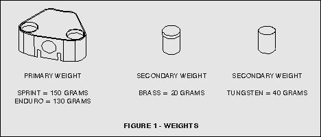
Each of the six main weights have two .50 inch diameter holes that accommodate brass or tungsten cylinders for additional weight. Filling only one hole per weight or mixing brass and tungsten cylinders in the same main weight is acceptable but each of the six weights must have the same pattern to avoid vibration.
For sprint weights the .24 diameter springs are optional and fit inside the .43 diameter springs.
Change weights and springs as follows. It is not necessary to remove the clutch from the kart.
1. Drain the oil by removing both pressure plugs.
2. Loosen the shaft collar and slide it out of the way. Remove the hairpin cotter, link, and speed collar.
3. Remove the springs and weights from the housing. Be careful not to lose the spring caps.
4. Insert new springs and weights. Check the position of the weights on the pressure plate.
5. Lubricate the O-ring and the threads of the speed collar with oil and carefully thread it into the housing. Check the seal and O-ring for proper seating. Rotate the speed collar clockwise until it stops. DO NOT TIGHTEN.
6. Rotate the speed collar counterclockwise about 3/4 turn.
7. Replace the link, hairpin cotter, and shaft collar.
8. Replace the oil and the two pressure plugs.
9. Test the engagement speed on the track and refer to section "Changing Engagement RPM."
ENGAGEMENT RPM
For optimum performance the clutch should be set to engage the engine at its peak torque RPM.
CLUTCH DISC REPLACEMENT
The life of the clutch discs is determined by the condition of the lining material. The thickness of a disc is not an indicator of its condition. One or both of the following conditions will occur.
(1) The lining material is porous. Eventually the pores of the linings will be clogged with oxidized oil, metal shavings, and dirt. This contamination is usually not visible. Nevertheless it will adversely affect the frictional properties of the discs. The clutch will engage less efficiently and lap times will increase.
(2) The lining material will burn as a result of over slipping the clutch again affecting the frictional properties of the discs. When exposed to an excessive temperature the lining material will turn brown or black in color.
In either case the discs are damaged beyond repair and must be replaced.
MAINTENANCE
1. Check the oil level and condition often. Use caution when removing the pressure plugs. Pressure and temperature increases inside the clutch may cause the oil to spew out forcefully.
2. If the clutch oil is oxidized during a race, drain it immediately to prevent contamination of clutch discs.
3. Check seals and O-ring periodically for damage and brittleness that may cause leaks.
4. Check the "U" shaped link for cracks. High stresses develop in the link that eventually cause it to break. Replace it at regular intervals to prevent a catastrophic failure. Enduro clutches are especially prone to this type of failure.
One link is supplied with the clutch. An optional back-up link may be installed in the second set of link holes diametrically opposed to the first set.
5. Check clutch rings for glazing. Restore the matte finish of the clutch rings with 300 grit sandpaper. Wash thoroughly with soap and water.
6. Remove fretting on pressure plate ramps with very fine sandpaper.
TROUBLESHOOTING
1. RPM DROP - Check clutch oil quality. Oxidized oil causes clutch engagement to drop 500 RPMs or more. Change the clutch oil not the speed collar!
2. LARGE RPM INCREASE WITH SMALL CHANGE IN SPEED COLLAR - The speed collar is turned beyond its operational limit of 1.5 revolutions. The weights are contacting the housing instead of applying force to the pressure plate. Reduce actuating weight, increase spring stiffness, or increase gear ratio.
3. POOR ACCELERATION - multiple causes:
A. The engine is losing power, e.g., sticky piston ring, broken reed, wrong flex pipe length, change in weather, defective carburetor, etc.
B. The weights are too light. The speed collar is turned out a minimum of � turn when the proper amount of weight is installed.
C. The engagement RPM is too low. This clutch should be engaged at maximum engine torque unlike other clutches that engage hundreds of RPMs lower. Some engine/pipe combinations now produce peak torque above 11,000 RPMs!
4. SURGING - cyclic change in engine RPM caused by one or more of the following:
A. Low engagement speed. See 3C above.
B. Oxidized or poor quality clutch oil.
C. Glazed or contaminated clutch discs.
D. Damaged or worn parts especially the sliding surfaces of the speed collar, pressure plate, and weights.
E. Flex pipe that is too short or too long.
F. Lean carburetor, usually the low speed jet.
PATENT NO. 5,070,984